|
überarbeitet am 11.9.2010
|
the Modules of the SE-415 Transceiver
Transmitter
found in the top module. You will have to select the transmitting frequency using
the three tuning knobs of the transmitter main tuning oscillator, both oscillator
modules are interchangeable.
The transmitter can be set up to transmit a upper and a lower or two independant
sidebands with reduced carrier. In typical Army use, the transmitter gives
A1 / CW or telephony A3A signal in the lower sideband and FSK / radioteletype
channels F1a and F1b in the upper sideband.
You can switch the transmitting power from 10, 100 up to 1000 Watts Peff, the transmitting
tubes 4CX250B are air-cooled and antenna tuning is automated. |
 |
Receiver
- a triple conversion
heterodyne set with two different RF- / IF- amplifier strips used for antenna
diversity reception. The three main tuning knobs are used to control the reception
frequency, it is displayed by a mechanical digital readout similar to the one found
in the Collins R-390A with a dial accuracy of better then 100 Hz.
The SENSIBILITE control is used as RF gain control, the left meter will display
the signal strength, the right meter is used to tune the station exactly to the
carrier of the communicating set. With the switch "AUTOM.FREQUENZREGELUNG", the
signal is synchronised automatically with the communication station in FSK modes.
In the middle between the two meters, You usually find the typical Swiss Army
seven days movement Revue clock. Because it's finger's have radium colour,
You might find it difficult to export the set because of radiation restrictions,
but I consider the minimal radiation not as harmful. You might cover the clock
with a metal shields like the ones found on american R-390A sets - or You might
simply take the clock away and store it in a metal cabinet. |
 |
Signal Module
- the "central" or "command post" of the transceiver:
You find the connectors
for headphones and morse key here, the connector "MIKROTEL" is used for connecting
a telephone like handset with a PTT (push to talk) button.
The transmitting mode switch allows to switch to single or split frequency operation,
the setting for connections with another SE-415 and for contacting a SE-222 with
it's smaller frequency range and reception modes are colour coded.
The speaker switch is used to select the signal com,ing from the receiver or
to monitor the transmitted signal, the middle red button is the AF gain / volume button.
The signal control switch is also used to calibrate the third oscillator stage
of the main receiver and transmitter oscillators. |
 |
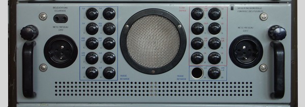
Power Supply Module
with an impressive number of fuses are used for the different voltages used in the set.
When the drawer is unlocked and pulled out, You find a circular switch and a meter
to perform a quick control, which of the fuses is blown.
Two 220 V sockets allow to operate additional gear, behind a metal grille in
the middle, You find the station's monitor speaker. |
 |
High Voltage module
here, You have acess to the fuses for the 1,8 kV plate voltage of the transmitter
and a operation hours meter. |
 |
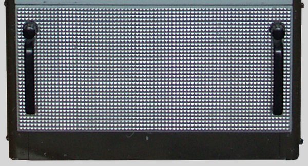
Connectors module
Behind the metal plate of the bottom drawer, You find
connectors for the mains, the mains 10Amp fuses, several connectors for using
teleprinters, the receiving and transmitter antennas, a wired remote control
and sockets for 12V DC and 220V AC to connect gear used in the radio shack. |
 |
|


